tekening van het elektrisch schema van een 110 of defender
tekening van het elektrisch schema van een 110 of defender
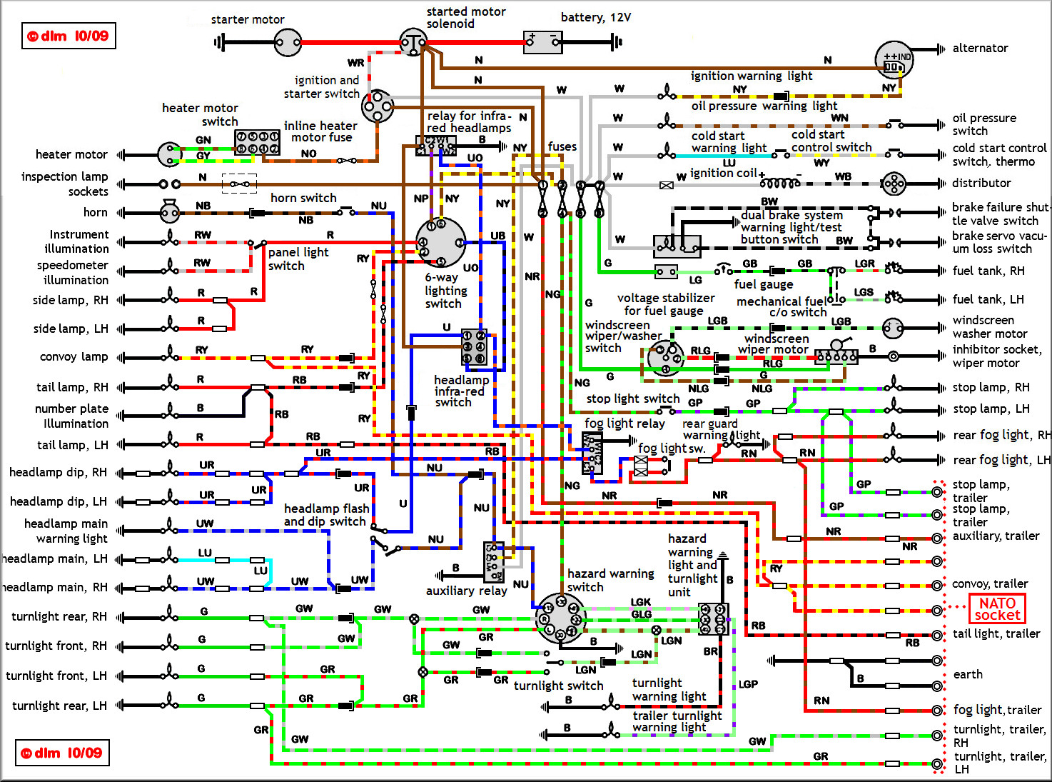
heeft iemand een tekening van het elektrisch schema van een 110 of defender
Re: tekening van het elektrisch schema van een 110 of defend
Verschilt nogal of je d'r een van 'n oneten, 200/300 tdi, td5 of puma wilt...
En ze zijn allemaal met een beetje goegelen zo te vinden op het www.
En ze zijn allemaal met een beetje goegelen zo te vinden op het www.
Vincent
1959 Polynorm 1/4 Ton Trailer, 195?, Olive Drab Green (verkocht)
1970 M416 Military Trailer (Kampeertrailer conversie), Epsom Green (verkocht)
1975 Series III 88 V6, Light Green (helaas verkocht)
1996 Defender 110 CSW 300 Tdi, Epsom Green (verkocht)
2000 Freelander 1 TD4 3-drs, Silver (verkocht)
2006 Freelander 1 TD4 5-drs Facelift Automaat, Tonga Green (verkocht)
> www.titunet.nl <
-
Landmarcs
- Berichten: 9292
- Lid geworden op: 09 Okt 2007, 20:59
- Locatie: Als het zo doorgaat, tzt aan zee
Re: tekening van het elektrisch schema van een 110 of defend
VeeTee schreef:Verschilt nogal of je d'r een van 'n oneten, 200/300 tdi, td5 of puma wilt...
En ze zijn allemaal met een beetje goegelen zo te vinden op het www.
En zelfs als je weet wat je "wilt", nl het schema dat vlgs het boekje bij jouw auto past dan kan de praktijk altijd nog weerbarstig zijn.
Mijn "puma" bleek in de praktijk volgens een ander schema in elkaar gezet als dat wat er vlgs de documentatie in moest zitten.
Groeten MarcS
Re: tekening van het elektrisch schema van een 110 of defend
ik wil de knipperalarmschakelaar en clignoteur aansluiten, heb de hele boel losgeknipt en nou weet ik het ff niet meer.
Re: tekening van het elektrisch schema van een 110 of defend
had hetzelfde probleem, na twee keer uitfikken wegens kortsluiting....
kwam erachter dat paars en groen lichten achter en alarmlichten zijn... oude glazen zekeringkast eruitgegooid en moderne steekzekeringenkast erin.
alles opnieuw aangesloten even zoeken en priegelen, maar ik kwam kroonsteentjes, van die ouderwetsche klemverbindingen ect. tegen.... raar is/was het niet dat er uiteindelijk iets kortsluit... zeker na een waterbad
veelal hanteren ze vanaf LW tot aan TD5 zelfde kleuren... idd even googelen..
manuals...
http://www.internet-tools.co.uk/blog/in ... nd-tricks/
kwam erachter dat paars en groen lichten achter en alarmlichten zijn... oude glazen zekeringkast eruitgegooid en moderne steekzekeringenkast erin.
alles opnieuw aangesloten
veelal hanteren ze vanaf LW tot aan TD5 zelfde kleuren... idd even googelen..
manuals...
http://www.internet-tools.co.uk/blog/in ... nd-tricks/
"Listen, smile, agree, and then do whatever the fuck you were gonna do anyway.”
― Robert Downey Jr.
'84-er 110, RHD, 200TDi; 2x lier( <--/-->), 2"lift OME & nog steeds niet tevreden...
― Robert Downey Jr.
'84-er 110, RHD, 200TDi; 2x lier( <--/-->), 2"lift OME & nog steeds niet tevreden...
-
RobStewart

- Berichten: 2280
- Lid geworden op: 15 Mei 2011, 12:04
- Locatie: Roger Young Land Rover, Cornwall
- Contact:
Re: tekening van het elektrisch schema van een 110 of defend
... if I remember correctly then this is the one you need
Rob
 One Ten V8 Circuit Diagram.pdf
- (225.7 KiB) 613 keer gedownload
Rob
Aub alleen te reageren in het Nederlands
1949 1,6 Series I
1975 3,5 V8 Range Rover
1989 3,5 V8 Discovery
2010 Td4e GS Freelander 2
2008 Td4 GS Freelander 2 ... yes we now have two
1949 1,6 Series I
1975 3,5 V8 Range Rover
1989 3,5 V8 Discovery
2010 Td4e GS Freelander 2
2008 Td4 GS Freelander 2 ... yes we now have two
Re: tekening van het elektrisch schema van een 110 of defend
thx mannen, beide top, met kleur is voor mij denk ik de makkelijkste 
Re: tekening van het elektrisch schema van een 110 of defend
ik heb zelf hier een hoop aan gehad....
http://forums.lr4x4.com/index.php?showtopic=13675
http://forums.lr4x4.com/index.php?showtopic=13675
I dont know the X-Charge system, but all split charge systems basicly functions more or less the same way.
Some kind of signal is used to trigger a solenoid so that the main battery and aux battery is joined together.
The signal for this solenoid can be taken from the alternator - or from any ignition switched supply. Taking the signal from the alternator is probably the best.
If you take the trigger signal from the alternator then the two batteries will only be joined together WHEN the alternator is charging. If you take the signal from an ignition swithed supply the two batteries will be joined together whenever the ignition key is turned - regardless of the alternator is charging or not.
By taking the signal from the green wire going to the rear wiper you have effectivly created a ignition switched split charge, instead of a alternator switched split charge system.
(Green wires are ignition switched according to wiring standard BS-AU7 - se below for full list)
On the alternator you will find at least three terminals, the big B+ where you connect the positive lead from the battery (joined at common point on starter solenoid) and the W+ where you connect the tachometer and the D+ where you connect the charge warning lamp.
The D+ is actually a lower rated "copy" of the B+ circut. The main purpose of the D+ circut is to provide input current to the regulator and to provide a positive feed for the charge warning lamp.
The charge warning lamp is on one side connected to the positive terminal on main battery, on the other side connected to the D+ terminal on alternator. When the alternator is not running, the regulator effectively shorts the D+ and field windings, thereby running a current from the positive battery terminal over the charge warning lamp to the alternator field windings and from there to vehicle earth. The charge warning lamp will then light up.
When the alternator is running the current provided from the main battery terminal will exite the field windings, and the alternator will begin to produce current. The charge warning lamp will then receive a positve feed from both sides which is why it stops to light after a few seconds after the engine is started.
The D+ terminal is therefore important for any split charge system, in providing a definitive signal for when the alternator is running.
Best practice is to connect the two wires ON the D+ terminal on the alternator. Then the modification is clearly visible for all others doing repair work to the car. The wire should (of course) be fused. 5amp fuse will be more than enough.
The two batteries (main and aux) should have common ground (vehicle earth)
A low cost split charge system can be made using a small 30 amp automotive solenoid.
Terminal 86 on the solenoid shoud be connected to D+ on the alternator. This wire will only provide a small current to trigger the solenoid so can be made from 1.5mm2 cable and should be fused with a 5 amp fuse (as close to the alternator D+ as possible)
Terminal 85 on the solenoid should be connected to vehicle earth (1,5mm2 cable will do fine)
Terminal 30 on the solenoid should be connected to main battery positive terminal. 30 amp fuse as close as possible to the positive terminal on battery. Use 6mm2 cable.
Terminal 87 on the solenoid should be connected to the aux battery postive terminal. 30 amp fuse as close as possible to the positive terminal on battery. Use 6mm2 cable.
The two batteries should both have their negative terminal connected to vehicle earth.
Full list of BS-AU7 colour codes included for reference purposes:
BS-AU7:
=========
Black: All ground connections
Black/ Purple: Temperature switch to warning light
Black/ Green: Relay to radiator fan motor
Black/ Light green: Brake switch
Black/ Light green: Brake differential pressure valve to warning light
Blue: Headlamp connections
Blue: Headlamp switch to dimmer switch
Blue White: Headlight high beams
Blue/ White: High beam dimmer switch to high beam indicator lamp
Blue/ White: Dimmer switch to long-range driving light switch
Blue/ Red: Headlight low beams
Brown: Main feed from the battery. No switches or fuses
Brown/Yellow: GEN to volt. Regulator
Brown/ Blue: power feed to headlamp switch
Brown/ White: Ammeter to main alternator terminal
Brown/ Yellow: Long-range driving light switch to lamp
Brown/ Yellow: Alternator to 'no charge' warning light
Brown/ Purple: Alternator Regulator feed
Brown/ Green: Fuse to horn (No relay)
Brown/ Lt. Green: Windscreen wiper motor to switch
Brown/ Black: Horn to horn button (no relay)
Green: Ignition switch controlled wiring for auxiliary devices, eg wipers, flashers, etc
Green/ Black: Fuel gauge to fuel tank unit
Green/ Blue: Water temperature gauge to temperature sender unit
Green/ Brown: Switch to reverse lamp
Green/ Red: Direction indicator switch to left-hand flasher lamps
Green/ Purple: Stop lamp switch to stop lamps
Green/ White: Direction indicator switch to right hand flasher lamps
Green/ Yellow: Heater switch to slow speed on heater motor or for single speed motor
Green/ Gray: Heater switch to high speed on heater motor
Green/ Orange: Low fuel level switch to warning light
Light green: voltage stabilizer to instruments
Light green/ Black: Windscreen washer switch to motor
Light green/ Blue: Flasher switch to left-hand flasher warning light
Light green/ Brown: Flasher switch to flasher unit
Light green/ Purple: Flasher unit to flasher warning light
Light green/ Orange: Rear window washer switch to motor
Orange: Wiper circuit
Orange/ Black: Wiper switch to to motor parking
Orange/ Blue: wiper switch to low speed on motor
Orange/ Green: Wiper switch to high speed on motor
Orange/ Yellow: Rear wiper switch to rear wiper motor
Orange/ Light green: switch to rear window motor parking
Purple: Accessories fed direct from battery via fuse (Always live)
Purple/ Brown: Horn fuse to horn relay when horn is fused separately
Purple/ Red: Switches to map light, under bonnet light, glove box light and boot lamp when fed direct from battery fuse
Red: Tail lights, instrument lights, parking lights and side markers
Red/ Yellow: Fog light switch to fog light or front fog light fuse to fog lights
Red/ Blue: Front fog light fuse to fog light switch
Red/ Brown: Rear fog guard switch to lamps
Red Orange: Power to rear fog guard lamp fuse
Red/ White: Fuse to instrument lamp switch, Instrument panel lamps
White: Ignition circuit, no additional switches, not fused
White: Power to coil
White/ Black: Ignition coil to distributor
White/ Black: Distributor side of coil to tech impulse sensor
White/ Brown: Oil pressure switch to warning light or gauge
White/ Pink: Ignition switch to radio fuse
White/ Red: Ignition switch or starter switch to starter solenoid
Yellow: Generator connections wired through the ignition switch
Yellow/ Green: Dynamo 'F' to control box 'F' Alternator field 'F' to control box 'F'
"Listen, smile, agree, and then do whatever the fuck you were gonna do anyway.”
― Robert Downey Jr.
'84-er 110, RHD, 200TDi; 2x lier( <--/-->), 2"lift OME & nog steeds niet tevreden...
― Robert Downey Jr.
'84-er 110, RHD, 200TDi; 2x lier( <--/-->), 2"lift OME & nog steeds niet tevreden...
Re: tekening van het elektrisch schema van een 110 of defend
allen bedankt, ik kom er nu wel uit denk ik. 
Wie is er online
Gebruikers op dit forum: Geen geregistreerde gebruikers en 33 gasten